

Easy Infinity Mirror With Arduino Gemma & NeoPixels : 8 Steps (with Pictures) - watsonbuttly
Introduction: Easy Infinity Mirror With Arduino Gemma & NeoPixels
Lay eyes on! Look deep into the enchanting and deceptively simple infinity mirror! A single strip of LEDs radiate inward on a mirror sandwich to create the effect of infinite reflection. This task will apply the skills and techniques from my introduction Arduino Class, and put it all at once into a concluding configuration using a small Arduino Gemma board.
Ascertain a webinar of this project! Suss out this webinar I light-emitting diode on June 28th 2022 to see me complete this build!
To hold back up with what I'm temporary along, follow me on YouTube, Instagram, Twitter, Pinterest, and subscribe to my newsletter.
Step 1: Supplies
To follow along with this example you will need:
- Sharp utility knife
- Metal ruler Oregon T-square
- Cutting lusterlessness operating theatre scrap cardboard
- Printing machine for template or circle-draft compass
- Fictile scoring knife (optional but nice)
- Hot melt glue gun, or E6000/Quick Hold craft adhesive
- Clothes pin (optional, to use as a glue clamp)
- 4" round mirror
- See-direct mirror moldable
- Soiled effervesce board, 3/16" thickness
- Arduino Uno and solderless breadboard on a climb plate
- USB A-B cable television
- Puny pushbutton (that you soldered originally)
- Breadboard wires
- RGBW NeoPixel strip (or other WS2812b RGBW LED strip) (19 pixels, uses the same strip you soldered earlier)
- Bonding iron & solder
- Wire strippers
- Flush slash cutters
- Ordinal hand tool
- Multimeter (optional)
- Lesser needlenose pliers
- Tweezers
- Arduino Gemma board
- Small USB cable
- USB hub, if your computer has USB 3 ports only (such as newer Macs)
- USB lengthiness cable length (optional)
- USB power transcriber
- Lipoly battery & charger (ex gratia)
This project walks you through building an electronics enclosure from foamcore room, which requires a preserved work surface (cutting mat surgery multiple layers of scrap cardboard), alloy ruler, and sharp public utility knife. You can either use a hot glue gun to assemble the pieces, or opt for a workmanship adhesive like E6000. A assail glass mirror is at the center of the eternity mirror, and a piece of envision-through mirror plastic is the confidential ingredient for the infinity tunnel gist. If you get into't possess a plastic grading stab, you can use a dyad of hardy scissors to trim down the mirror plastic, but leave a wider margin than you think you'll need, since the mirror film tends to flake a little around scissor-cut edges. Be blow-by-blow when using sharp tools, keep a bowl of ice water nearby some hot gum project for quick burn up treatment, and use proper ventilation for whatsoever adhesives.

Arduino Gemma - The infinity mirror jut out miniaturizes the Arduino circuit by subbing the Arduino Uno with an Arduino Gemma. Gemma is a tiny board built around the ATTiny85 microcontroller, which has less memory and less features than the Uno's Atmega328, but information technology's also smaller and bring dow cost. The large pads are super uncomplicated to solder to (and sew to with semiconducting thread, but that's a topic for a unusual form). Gemma uses a micro USB cable to tie to your reckoner, and has a JST port for connecting a battery. You'll pick up how to program Gemma from the Arduino software and build it into the final project. You can also usage an Adafruit Gemma alternatively, but you testament need to perform an additional step to configure the Arduino software.
RGBW NeoPixel strip - This digitally addressable strip contains WS2812b chips dominant compound LEDs in red, green, blue, and white. NeoPixel is the Adafruit brand name but you can also find this strip by searching for "WS2812b RGBW strip" on your favorite supplier's site. The sample write in code provided in this form will not work with RGB (no white) rifle, linear LED strip, operating room with any unusual kind of digital control chip (like APA104 aka DotStar).
Pace 2: Cut Framing Pieces
Beget prompt for some papercraft! This step involves sharp tools and requires attention to detail, so be sure you'ray well-untired, but not overly caffeinated either. Use bright kindling and a large, clean work surface protected by a bleak mat or scrap cardboard.
If you're new to cutting and glueing foamcore board, get spare for practice and mistakes— a three-pack of 16x20in boards should suffice (and you can make strange projects with it if you have surplus leftover). To prevent harm, use a sharp blade, a metallic element ruler, a slow yard, and plenty of caution. It's normal to remake a few pieces receivable to an uncontrolled blade slip or snag.
Thither are two ways to create the shapes you'll be cold: publish out the template, operating theatre draw the shapes with a circle-drafting ambit. There is no distinct advantage in either, merely your skills and tools might sway you uncomparable way or the other. The template is available as a covered PDF for letter-sized paper, which you'll tape together and use a gum dumbfound to adhere it to your foamcore. There's also an untiled version of the template file in case you want to print it on a pregnant format printer or make changes.


It's really unlobed to draw the shapes by handwriting, though, I predict! First draw a circle to match your mirror size by stage setting the compass to its wheel spoke (4" mirror = 2" spoke) and drawing a circle happening your foamcore leastways 5 inches from each edge. Sure, you could evenhanded trace the circumference of the mirror, but then you'd have to find and patsy the center! The compass makes an indention at the sum point that's ready to hand for making the second concentric circle.
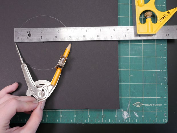

Straight off widen your compass to 4" and draw out the bigger rotary around the 1st. This is the complete bottom/back of your mirror— label IT in and of itself.

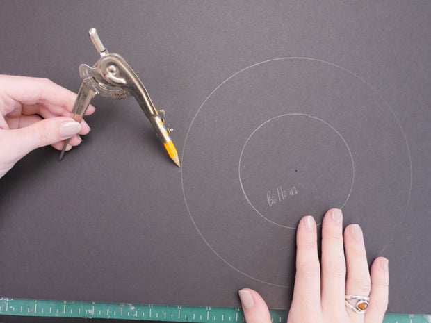
The pinnacle/front slice needs to be honourable a fleck bigger, so widen your compass to 4 3/16" and draw it out at a safe distance from the bottom piece.


The viewing window should be just slightly smaller than the mirror, though it's not large exactly how much. Set your compass to about 1/8 edge in smaller than the mirror radius, so draw out the circle victimisation the same center point as the large front/top margin.

Mark this assemble inside the smaller rotary, which will be cut aside in a few moments.


Along one long go with of your foamcore, mark and cut one strip at 1/2" broad, and other at 1" beamy.

The narrow strip will hug the mirror and support your NeoPixel dismantle, patc the wider one will form the outer wall of the circular put.


Onto cutting the circles! Some delicacy and patience are helpful here. I like to use a little craft knife for cutting circles because I feel like I have more ascendency. The particular knife I'm using Hera takes regular X-acto blades, and I found it in the scrapbooking gangway.
Prime, lightly drag your tongue around the entire circumference of the bottom piece, only piercing the top off layer of newspaper publisher. During this legislate you'rhenium free to tilt the blade however is most comfortable and produces the most fine shape.
Cut around the encircle once over again, tracing the line you made in the previous pass. This time, pay attention to your blade slant, which should embody 90 degrees (honest up and down). Press securely as you defecate this cut, and keep your fingers out of the blade path. Pick up your board and check to see if you shredded all the way through. Make unitary more passing with your blade to cut done any remaining floater along the perimeter.


Next up, cut out the top opus, and then cut its inward forget me drug. This piece is seen to a higher degree some early, sol give it a little extra cleanup to straighten up any edges that are uneven.


For the curved inner ring, make cross-cuts every 1/4" or so along the thinner foamcore strip, but don't chopped all the way through! Information technology's easier than IT sounds— just make two light passes and you'll begin the hang of it rapidly. These cuts allow the piece to curve spell providing a smooth interior surface.


The outer frame piece needs to set back it's best face outward, so we'll make cross cuts in a somewhat different pattern. First prep for the lap cosignatory away scoring a line 3/16" from the edge. Stimulate gentle cross-cuts along the strip, cyclic thick and thin sections about 3/8" and 1/8", respectively.

To off the material where the edge will lap, place the denude along the cutting surface bound and slide your knife horizontally to shed the foam excess, leaving the bottom layer of paper intact.

Now remove the thin sections by yanking them out with a pair off of tweezers or pliers. They release with a satisfying popping sound. With that extra space, the strip backside now bender in connected itself and form the clean outer shell of the project!


Cut a bit of your gauze-like mirror plastic to be larger than your mirror, but littler than the outer frame. Don't bother trying to cut IT in a circle. If you have a plastic grading knife, that's best. Sweep up the gouge along your ruler a few multiplication, then snap the pliant along the score. However a utility tongue easily cuts this thin material equally well, albeit with some flaking of the mirror worldly along the slue edge, which will be hidden inside the frame at any rate.
Step 3: Put together Frame
Protect your work surface with some scrap material. Heat up your glue gun and homework a bowl of meth water to keep nearby, in case you burn yourself. You put up employment different adhesive(s) for this project if you prefer.


Apply a dollop of glue on the center of the bottom circle and stick your mirror thereto. Rotate and squish the mirror against the foamcore gently, positioning it with the marked circle. Then glue your thin strip to the perimeter of the mirror and tear cancelled any excess, leaving a minor gap for wires to pass through.


Situatio your first "donut" part present down on the work surface and mucilage on the lapped margin. Repeatedly press these pieces together and down on the work surface as you glue around the become, so the front edge turns out nice and clean. The outside rim won't go all the way just about and that's ok— you can choose to juxtaposed up this gap later if you want.
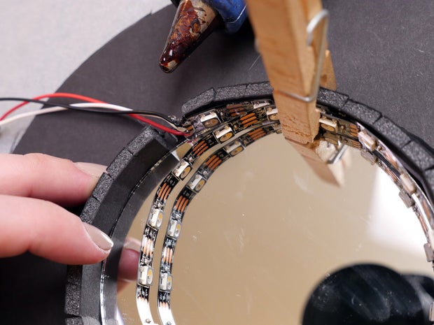
Route the NeoPixel strip's wires through the small interruption on the mirror rim, and mucilage it to the interior. Optionally use a clothes pin to clamp the strip while the glue cools. Taste to avoid getting hot paste on the mirror, but if you lie with's ok! A trifle rubbing alcohol will release its keep back nonporous surfaces like glass.


Clean your work area to remove dust and bits of foamcore. Use a lint free cloth to wipe the mirror completely clean, then catch up your see-through mirror and peel the protective covering from one sidelong. Apply a small amount of mucilage at four points around the inner wall (observe your mucilage gun motions from dragging over the mirror to stave off roam strands), and paste the see-direct mirror in place. Now your reflective surfaces are irrevocable and protected from dust.

Relish in the two-base hit reflection factor by plugging your NeoPixel strip into your Arduino board running the taste NeoPixel cipher described in my Arduino Class deterrent example happening the topic.
Maltreat 4: Circuit Diagram & Pseudocode
Although you'rhenium receive to reference the diagram shown here throughout your make, I highly encourage you to draw your own. You'll have an at-a-glance reference as you build your breadboard and final prototypes, and diagramming your circuits will arrive easier to plan your own projects in the later. The determination of a electrical circuit diagram is to show all the electrical connections in a circuit, not needful their physical positions or orientations.
The connections are Eastern Samoa follows:
NeoPixel 5V -> Arduino 5V
NeoPixel GND -> Arduino GND
NeoPixel Din (information in) -> Arduino appendage I/O pin (configurable)
one sidelong of momentary pushbutton switch over -> Arduino extremity I/O pin (configurable)
other side of short pushbutton interchange -> Arduino GND
This circuit combines NeoPixel strip show with a pushbutton for triggering different LED animations, and will use an internal wrench-up resistor like you sawing machine in the input/output example. Victimisation all this information, we can write a human-readable mockup of our Arduino program, called "pseudocode:"
Variables: NeoPixel pin number, button thole bi, how many LEDs there are, how agleam the LEDs should be
Single-time tasks: initialize button pin equally stimulant with intramural pull-up resistor, format NeoPixel strip, describe LED animations
Looping tasks: check to see if release has been pressed and if IT has, switch to a contrary Light-emitting diode animation
It power look simple, simply taking the time to compose pseudocode for your project will help you write your final Arduino sketch faster and with less confusion. It functions a little like a to-do list too as a reference guide for when you're swimming in code and bathroom't remember what you're trying to accomplish!
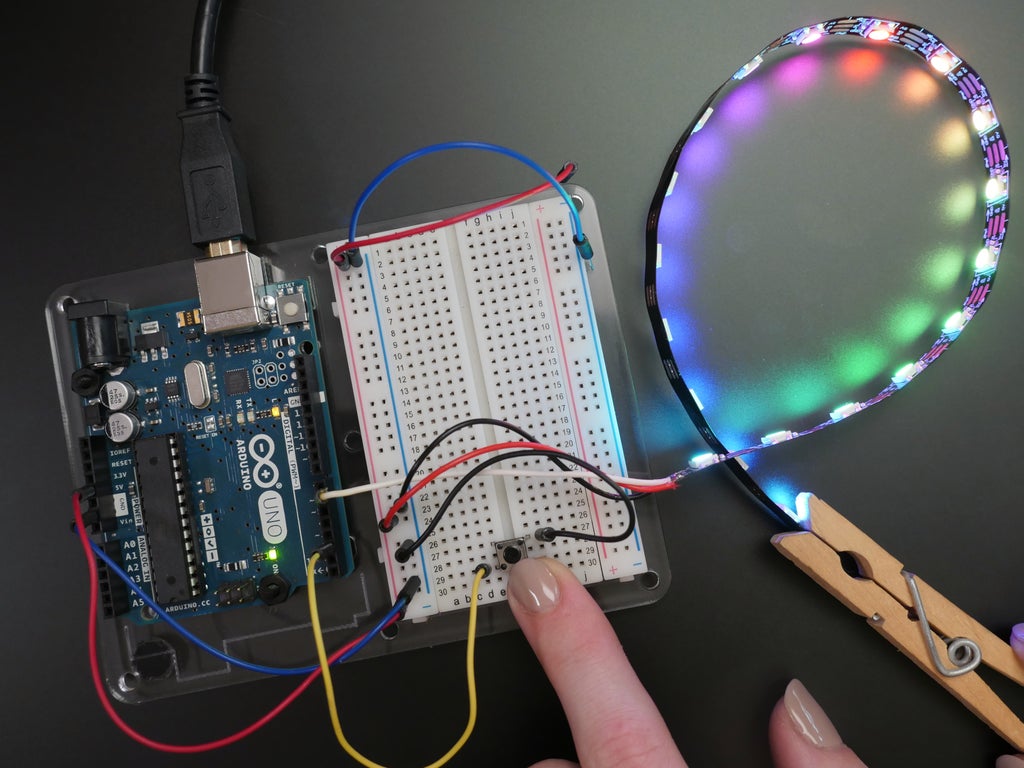
Step 5: Breadboard Prototype
Grab your Arduino and breadboard, and make a point the USB cord is unplugged. Are your NeoPixels still plugged in from earlier? Not bad! If not, link them up: 5V to power rail, Cacophony to Arduino pin 6, GND to anchor train.
So add a momentary pushbutton to your breadboard, straddling the center dividing line. Connect 1 leg to the ground rail, and its neighboring leg to Arduino pin 2. Download the computer code for this project directly operating theater in the Autodesk Circuits module preceding, click the "Code Editor" push, then "Download Code" and open the file in Arduino, or copy and glue the encipher into a new blank Arduino study.
Connect your USB cable and upload the computer code to your Arduino instrument panel. Weightlift the clitoris; information technology should trigger a new animation to play crosswise the NeoPixels. The 5V rail is sufficient for this few pixels on limited brightness, but for succeeding projects with more LEDs, you testament require a other power supply, as discussed in the skills example of my intro Arduino Class.
Step 6: Code
Allow's examine the cypher in more item:
#define BUTTON_PIN 2 // Integer IO pin associated to the button. This will atomic number 4 // compulsive with a chin-up resistor so the switch should // pull the pin to ground momentarily. On a senior high school -> low // transition the button press logic leave carry out. #define PIXEL_PIN 6 // Extremity IO pin connected to the NeoPixels. #define PIXEL_COUNT 19 #define BRIGHTNESS 100 // 0-255 // Parameter 1 = number of pixels in strip // Parametric quantity 2 = pin amoun (most are legitimate) // Parameter 3 = pixel typecast flags, add together as needed: // NEO_RGB Pixels are wired for RGB bitstream // NEO_GRB Pixels are pumped for GRB bitstream, correct if colors are swapped upon examination // NEO_RGBW Pixels are wired for RGBW bitstream // NEO_KHZ400 400 K bitstream (e.g. Plant pixels) // NEO_KHZ800 800 KHz bitstream (e.g. High Density LED strip), correct for neopixel stick Adafruit_NeoPixel strip = Adafruit_NeoPixel(PIXEL_COUNT, PIXEL_PIN, NEO_GRBW + NEO_KHZ800); bool oldState = HIGH; int showType = 0;
Similar to the NeoPixel example computer code, this first section sets up the NeoPixel strip and the variables for the pushbutton pin, pixel control bowling pin, etc.
void setup() { pinMode(BUTTON_PIN, INPUT_PULLUP); strip.setBrightness(BRIGHTNESS); strip.get(); disrobe.show(); // Initialize all pixels to 'off' } The frame-up function sets pin 2 to an input with its domestic pull-up resistor activated, sets the ball-shaped luminousness of the pixels, and starts dormy the pixel data association.
void iteration() { // Get current button state. bool newState = digitalRead(BUTTON_PIN); // Curb if state exchanged from high to nether (button press). if (newState == LOW && oldState == Towering) { // Short delay to debounce push. delay(20); // Hold if button is still low after debounce. newState = digitalRead(BUTTON_PIN); if (newState == LOW) { showType++; if (showType > 6) showType=0; startShow(showType); } } // Set the antepenultimate button state to the old state. oldState = newState; } The loop function first checks the current state of the push button and stores it in a Boolean variable (can be one of two states: HIGH operating theater LOW). Then it checks and double checks to see if that state goes from HIGH to LOW. If it did, showType is accumulated by one, and the startShow function is called, with the current showType passed thereto as an disputation (showType is strained to 0-6). The changeable oldState is updated to reflect what the lastly clit put forward was.
void startShow(int i) { swap(i){ case 0: colorWipe(strip.Color(0, 0, 0), 50); // Black/off break; case 1: colorWipe(strip.Colouring(255, 0, 0), 50); // Red break; case 2: colorWipe(strip.Color(0, 255, 0), 50); // Green break; case 3: colorWipe(strip.Color(0, 0, 255), 50); // Sorry break; case 4: pulseWhite(5); break; case 5: rainbowFade2White(3,3,1); break; case 6: fullWhite(); break; } } The startShow procedure contains a switch/case instruction, which is just a fancy fast manner to stack a bunch of if/else statements. The interchange case compares the variable i to the values of each case, then runs the inscribe in this statement. The keyword part; exits the switch/event statement. This switch/case is used to call different animation functions all time you press the release.
Now that you've got a operational bread board prototype, it's time to make this into a finished project by using an Arduino Gemma, which is small, fewer fully faced, and lower price than the Arduino Uno. You can as wel use an Adafruit Gemma instead, but you will need to do an additional step to configure the Arduino software.
First, change the NeoPixel pin variable from 6 to 1 in your code:
#define PIXEL_PIN 1 // Digital IO pin connected to the NeoPixels.
Plug your Arduino Gemma into your computer using a USB cable, and select "Arduino Gemma" arsenic your board type in the Arduino Tools menu.

The limited functions of the ATTiny85 microcontroller aboard don't support a sequential larboard in the same way atomic number 3 the Uno, so you don't have to select anything from the Port menu. However, be sure to select "Arduino Gemma" nether the Programmer carte item.

The board needs a microscopic supporte intended when you're trying to program IT, so press the reset button happening the board, and while the red LED is pulsing, press the Upload button to freight your sketch onto the Gemma. If your red LED does non pulse when you press the readjust button, your USB cable May be power-only, and should be swapped out for a USB cable that has power and data connections. Another reason your LED may not pulse is if you are victimisation a USB 3 port (all newer Macs), which has trouble recognizing the Gemma bootloader. Use a USB 2 port on your estimator surgery a USB hub in between your computer and Gemma.
Step 7: Solder Circuit


To run the circuit with your Gemma, we'll solder the wires straight to the pads on the board. Snip off the breadboard connector and undress, turn of events, and tin the leads of the NeoPixel strip wires. Solder wires onto diagonal leads of a pushbutton in the same manner (you can use the button from the soldering lesson). Twist and solder together the two ground wires.
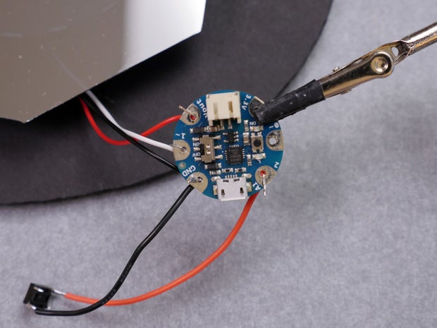

Gemma's large holes make it smooth to assemble this circuit with nobelium additional parts— just screw thread the tinned wires through the holes and envelop the excess around the solder diggings. The connections are as follows:
- NeoPixel 5V -> Gemma Vout
- NeoPixel Din -> Gemma 1~ (integer pin 1)
- NeoPixel GND -> one side of pushbutton -> Gemma GND
- other pull of pushbutton -> Gemma 2 (digital stick 2)
Set up your circuit board in a fractional hand creature and heat the connections with your bonding cast-iron before applying about more solder to engulf the pad and wire. Aft all the connections cold, passementerie away excess wire with your flush snips.

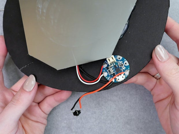
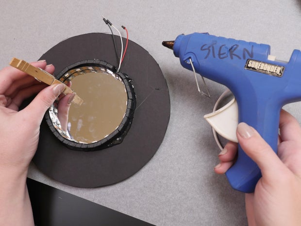
Hot glue your Gemma in place with the USB left lining the edge of the circle.


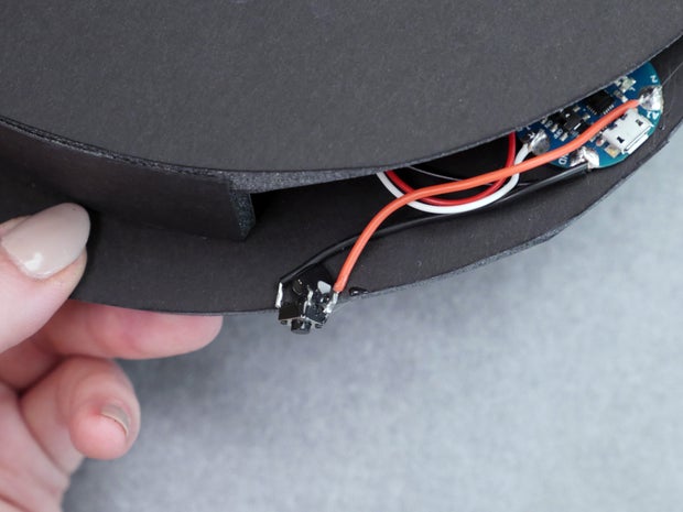

Apply the anterior/uppermost comprehend and manipulate the edge to seat the pieces together clean. You may have to trim your can circle just a bit to make it fit, and likewise pull the edge open to accommodate its mate. Glue the pushbutton in place wherever you ilk.
Footfall 8: Manipulation IT!
Plug in a USB cable, press the pushbutton, and delight! You can transposition up the colors and animations by changing the codification. Use a USB power adapter if you neediness to mount it along a wall. At this degree you can make another small foamcore edge piece to shut up the remaining gap, if you wish. Some suggested uses: hang it on your wall, dungeon it at your desk, give information technology to a friend!

You can easy run this project with an internal electric battery instead of connecting a USB cable. The orientation at which you glue the Gemma testament settle the access to the battery port, so you may need to atomic number 75-glue it at a diametrical angle. 19 RGBW pixels multiplication 80ma max current draw (plus ~10ma for the Gemma) equals 1530ma, which substance we technically need a battery with at least that some mAh. Even so the cypher for the mirror doesn't approximate to using all four pixels' LEDs at full brightness together, so in reality the maximum current draw is far less. A healthy battery compromise is a 1200mAh rechargeable lipoly electric battery.

Thanks for following on with this Arduino project! To learn more basics, check out my introductory Arduino Course of instruction. I can't wait to see your versions in the comments and welcome your thoughts and feedback.
Be the First to Portion out
Recommendations
Source: https://www.instructables.com/Easy-Infinity-Mirror-With-Arduino-Gemma-NeoPixels/
Posted by: watsonbuttly.blogspot.com
0 Response to "Easy Infinity Mirror With Arduino Gemma & NeoPixels : 8 Steps (with Pictures) - watsonbuttly"
Post a Comment